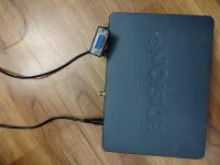
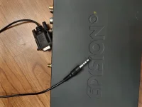
Edision MIO RS232 Connection

Well dammit. Did it before. Now I have a brick. Help maybe?
My splash was openatv. Was for a long time. Tried to flash the Edision spalsh (just when the osmio4k boots).
After. It stuck on 50% booting like forever. I cut the power to it, pulled the USB. Plugged it back in.
Nothing. Blank screen. But something appears to be going on inside because the IR blaster lights up for a few seconds and my ASC1 display comes on until it times out.
Couldn't happen at a better time, huh!
Read around hear and there. Mainly here for an unbrick.
Tips from you EB on a serial, RS232 recovery. Yeah I plugged it in and hit the menu key on the remote rapidly. No joy.
May I say....CRAP!
Is there a method to try using the serial port. I didn't crack the receiver open to see if there is a pinout silkscreened. Is it a 3 pin port? Rx/Tx/Gnd?
If there is a way to try to bring life back in this critter. Is there a pinout available? And a guide to flash what I guess would be the bootloader? I have that on a stick ready to go.
That is if I can get a terminal at least connected. Baud rates, etc?
Unbelievable.
 
The same file that worked some time back:
https://legitfta.com/forum/showthread.php?26647-Restore-Factory-Edision-Boot-Logo-for-OSMIO4K

The PS checks fine and can supply adequate current. Of course you know that's the first place I went.

As mentioned. It was working just fine. When the USB was in. I booted it. It displayed boot and then flsh just like normal when loading an image.
Then went to 50% and hung for maybe 5 minutes. Before it was instant. I remember that.
Yeah even used another 12 vdc supply with the same specs. Known good.

It's morning now. Was unplugged from everything all night. Same deal. Plug it in and the ir blaster comes on for a few seconds and ASC1 display pops on. Box is dead, dead.

So. RS232 flash is mentioned. I need to make a cable. Yeah. I've flashed routers, hdd firmware.
They put the port on it. And mention 'for flashing firmware'. Is there a so, how do I do it anywhere at all?

I'd like to at least see if the cfe is still kicking. dammit. I'm positive here. But pissed. Just when the fat man raised prices and was considering a 4k+.
 
RS232 connection settings are standard. 115200 for the baud rate, then leave everything else at default. I use RS232 at times for debugging. Before you try RS232, check and see if the receiver is trying to make a network connection. i doubt it is with no display lights on the front, but check for network connection first by doing a search with the receiver connected.

RS232 connections on the MIO receivers are made using an audio type plug. You probably only need TX, RX, and GND.
 
RS232 connection settings are standard. 115200 for the baud rate, then leave everything else at default. I use RS232 at times for debugging. Before you try RS232, check and see if the receiver is trying to make a network connection. i doubt it is with no display lights on the front, but check for network connection first by doing a search with the receiver connected.

RS232 connections on the MIO receivers are made using an audio type plug. You probably only need TX, RX, and GND.

Exactly. Nope no network, no putty login. I was searching for the loader tool if there is one. Obviously there is someplace.
And using a lan scanner application. Nothing. The Ethernet port looks dead with no flashy led's. Since it's dead I don't think a crossover cable will even help.
Looking at different 1/8" tip/ring/sleeve, trs, rs232 wiring schemes.
Some have the tx at tip, others rx at tip. and some use no ground but use the cts on the sleeve. And then others have the tx/rx wires tied to the same point either on the tip or ring.
yaaaaaa!!!
Perhaps a pad on the board. I dunno. But a loader to blow in binaries. And if the bootloader is corrupt or just the image firmware.
EB you might know that. If an image is borked do we still get the boot display? Or can a puked image also make for a dead display?

I mean. For now I do have a Zgemma H7. Probably could have an equal to a mio4k+ if I could make a decision and find one. Or a TBS card came to mind also. What the hell, right? 2 ports is all I would really need. Thoughts on one that doesn't cost an arm and a liver until I get the serial flash method and procedure for the mio sorted?
<cussing bad stuff under my breath with a positive attitude. lol!

Edit:
Pls don't get peed. I might hit up satuni and ask them . I brace myself for abuse. You know....programmers and soap boxes.
 
Exactly. Nope no network, no putty login. I was searching for the loader tool if there is one. Obviously there is someplace.
And using a lan scanner application. Nothing. The Ethernet port looks dead with no flashy led's. Since it's dead I don't think a crossover cable will even help.
Looking at different 1/8" tip/ring/sleeve, trs, rs232 wiring schemes.
Some have the tx at tip, others rx at tip. and some use no ground but use the cts on the sleeve. And then others have the tx/rx wires tied to the same point either on the tip or ring.
yaaaaaa!!!
Perhaps a pad on the board. I dunno. But a loader to blow in binaries. And if the bootloader is corrupt or just the image firmware.
EB you might know that. If an image is borked do we still get the boot display? Or can a puked image also make for a dead display?

I mean. For now I do have a Zgemma H7. Probably could have an equal to a mio4k+ if I could make a decision and find one. Or a TBS card came to mind also. What the hell, right? 2 ports is all I would really need. Thoughts on one that doesn't cost an arm and a liver until I get the serial flash method and procedure for the mio sorted?
<cussing bad stuff under my breath with a positive attitude. lol!

Edit:
Pls don't get peed. I might hit up satuni and ask them . I brace myself for abuse. You know....programmers and soap boxes.

Did you try the usb emmc flash? Extract the Tnap 5 usb image to a flash drive then open it and rename noforce file to force.
 
No joy. Renamed noforce to force. Sent to a fresh formatted USB that I know is good.
USB in, power plugged in. Nothing. Only thing is the right amber led on the Ethernet port lights for a few seconds.
Dead display. Tried punching the menu key on the remote when plugging in.
Tried the trusty old Linux router 30/30/30 trik. Nope.
Power supply putting out 12.22 VDC no load. A #192 bulb lights ok and voltage holds.
2 in parallel still light up ok. So ps is good.
She's dead. I think it has to do with the bootloader. And a serial flash is the last resort.
I know things happen.Deal with other peoples things every day. So not pointing fingers, but sure it wasn't me.
Crazy they put the port on it but don't document it. Stupid crazy.
 
No joy. Renamed noforce to force. Sent to a fresh formatted USB that I know is good.
USB in, power plugged in. Nothing. Only thing is the right amber led on the Ethernet port lights for a few seconds.
Dead display. Tried punching the menu key on the remote when plugging in.
Tried the trusty old Linux router 30/30/30 trik. Nope.
Power supply putting out 12.22 VDC no load. A #192 bulb lights ok and voltage holds.
2 in parallel still light up ok. So ps is good.
She's dead. I think it has to do with the bootloader. And a serial flash is the last resort.
I know things happen.Deal with other peoples things every day. So not pointing fingers, but sure it wasn't me.
Crazy they put the port on it but don't document it. Stupid crazy.

You lucky you got the usage out of the Mio that you got. Quite a few reports of failure over the last years. I've had two non plus Mio's go here as well.
 
It would be a good idea to see if any output can be seen through the RS232 port. Mainstream RS232 support for FTA receivers disappeared almost entirely around 10 years ago. Most home computers that have been made in the past ten years do not have a RS232 port, which means usb to RS232 adapters are needed. A lot of people have had problems with usb to RS232 adapters, especially using Windows operating system. Linux usually automatically finds and loads the needed drivers for usb to RS232 adapters, but usually not so with Windows.

There are cables available or used to be available on Ebay that will give a RS232 connection for the MIO receivers, but which one to buy can be a crap-shoot. I own several phone jack to RS232 cables, and RJ11 to RS232. Plus I have had to build several for different FTA receivers.

If you don't have the correct cable, then you will need to buy or make one.
It is possible to wire a RS232 cable where it shows data but will not accept data.
Then you have the null and straight issue where TX and RX need to be crossed. Almost all FTA receivers made within the last ten years are set for RX and TX to be crossed for cloning.

Trying to figure out wiring for RS232 connections on an injured receiver can be a challenge because you have no idea if the RS232 port is working. But usually only 3 wires are needed: RX. TX, GND. Understand where these three connections are on the computer. then all you have to do is figure out where they go on the receiver. Opening up the MIO may give a clue as to the order of the wiring. Sometimes the PC boards are labeled Otherwise, insert a phone jack into the back of the receiver and start going through the possible combinations. The receiver will have to be restarted every time a new combination is tested.

The cable I use for MIO RS232 plugs directly into the receiver and computer. Life is easier with a built-in RS232 port on the computer. Some RS232 usb adapters are straight while others are null. The RS232 connection in 2023 is beyond the capability of the average user, so very little information is available for it. A bootloader for the MIO exists in a download. But there are no instructions for installing it through RS232.

I cannot recall trashing a bootloader on an enigma2 receiver. I have been using enigma2 receivers for a good 10 years and am very rough on them. I also collect them. Usually when the bootloader quits in an enigma2 receiver, there was some other problem besides the bootloader. This is part of the enigma2 receiver that is hard to destroy.

IMG_20230804_194721_hdr.webp

IMG_20230804_194733_hdr.webp

IMG_20230804_194737_hdr.webp
 
Thanks. Most of what you stated is what I deal with a lot.
Couple of things. Since it looks like you have a cable that works would you be able to use a multimeter and check if we have the following. The DB9 shell pins should be marked whether M or F.
Pin 5 is ground and is probably the sleeve (closest to the molded housing and cord) of the 1/8" plug.
And what about pin 2, TXD and pin 3, RXD.
Which would be connected to the tip and which to the ring? No chance 2&3 are connected to the same place. Surprised me when I saw the different wiring schemes for them.
I have an Arduino which is great for serial flashes. And the FTDI cable that came with the ASC1. Both never fail.

Also I have to ask. You're obviously familiar with using the cable with the mio.
What do you use it for and what applications do you run when using it?
TFTP? Terminal session? Have you ever flashed an image using the port or bits of anything to the mio? Oh yeah. What baud rate so i don't get immediate gibberish.

In the morning I will tell if I can get any life out of the port. Usually just a switch of tx/rx lines if no coms (if it's gonna work) and then the bootloader sings out it's little song when powered up.
 
As already said, the baud rate is 115200 and everything else is default.
RS232 is useful for debugging. You can see usually where and why the receiver stopped. And many times file errors will be shown. RS232 was recently used to help solve the ATSC usb tuner problem in Octagon and other receivers. RS232 output is similar to the telnet debugging commands: init 4 && enigma2.

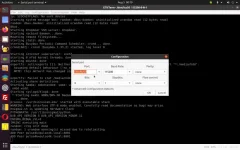
A sample RS232 debugging log is attached. The information is not useful to most people that own FTA receivers. It is possible to transfer small files through RS232, but that is not something I normally do. The files have to be small...

I can give you a pinout of my cable sometime tomorrow. I don't have the needed tools with me now. And if I remember right, two of the four pins on my cable are connected to GND. (Not 100% on this.)

Screenshot from 2023-08-05 00-19-31.webp


This thread needs to be split.
 

Attachments

Only 3 wires needed for RS232 connection. The tip of the phono connector is referred to as tip, then 2, 3, 4 as my phono plug has 4 positions.

pin 3 = Tip (1)
pin 5 = 2
pin 2 = 3
pin 5 = 4

Pins 3, 2, and 5 are used on the computer's RS 232 port.
Pin 3 = TX
Pin 2 = RX
Pin 5 = GND

TX is on the tip, GND is on 2 & 4, RX is on 3. If it doesn't work, swap RX and TX first. Receiver will need to be UN-powered and powered each time to see the RS232 output.

Screenshot from 2023-08-05 22-34-20.webp
 
You know what?
You're a good man. Will move this to a new thread as I progress. Or not.
Hoping to get it running again and maybe it will help others.
Thanks again.
 
So far here's what I have.

TIP: RX From receiver to cable
Ring 1: Ground
Ring 2: TX from receiver to cable
Sleeve: Ground

I think that matches what you wrote.
My FTDI cable went south. Tried to pull the recent positions from my ASC1 to store to a file. No response. Confused me.
Connected pin 2&3 of the DB9 and tried a loopback test. Then took a peek on my scope. No TX. So waiting a few replacements.
Win 11 tried to obsolete the Prolific chipset anyway and had to force older drivers. The ones coming are advertised to be ok with 11.
I do have a Linux laptop with DB9. Just too lazy to dig out a cable and fashion an "octopus" for it.

But. On the better side. I am able to see a data stream on the scope from ring 2. 5 data bursts when plugging the receiver in. Quite complex. Then it settles down.
No change when pressing the power button. Nothing when spraying it with IR from the remote. No change with a USB loaded with an image.
Located the Winbond SPI NOR flash. Promising. Last ditch is pull it and do a dump/compare. Bios flashing motherboards saves them usually when they come in bricked.

Satuni gives no response. Edision.gr support replied. Suggested I contact developers. And pointed me to the wrong 3 contact cable.
The tuner driver query back when impressed me. Not knowing how to use the com port to restore it is a big bummer.
The data burst shows me something is happening. So. Let's see.
 
The three contact cable is probably correct. I have a three contact cable somewhere that shows data. You only need three anyway, RX, TX, and GND. One of my receivers actually shipped with the correct serial cable.

A FTDI cable should be TTL, which is looking for 5 volts. If so, That cable is wrong. The best thing to have is a computer with a real DB9 serial port. Windows usb to serial connectors may/may not work as Windows is particular about drivers for the thing. Some usb to serial cables are TTL, but you don't find out this tidbit until you try to use it.

TX, GND, RX OR RX, GND, TX. One of those two should work when connected to real serial port.
 
Actually good points. Since the cable I had that Brian shipped with the ASC1 worked great for a few years. Pretty sure it was adhering to specs.
Looking further into the actual FTDI chips it looks like they auto negotiate voltages . Either 3.3 or 5V. Cool so far.
But a great time to measure peak to peak on what the short bursts are coming form the mio board.
I'm on a mission to try and save it. Too bad these stb guys don't follow router manufacturers like Asus and Netgear, Linksys and make them basically unbrickable.
Anyways. Located the Samsung emmc chip under the smart card slot and identified it. Just a bit giddy in methods to dump and flash binaries.
If in fact the factory boot screen flash hung and borked it. 100% positive it did. Dumping it and comparing it to the one intended to flash seems the way to go.
It's hard to believe that Edision ships out blank boxes and it's up to developers to burn an os.
And harder to believe they point out the port in the manual but have 0 support on how to use it.
Which was exactly what was stated in the reply to the email I got. In a very nice way, of course.
 
No voltage is used period. Only 3 pins, RX, TX, GND. This is why RS232 is written on the receiver port.

For some reason, you have decided that the bootloader is gone. So you are basing everything else on that assumption. Destroying a boorloader in a HEALTHY enigma2 receiver is a very hard thing to do. You have to work at it. This is why you don't see any bootloader support because it rarely happens. In some 10 years of playing with enigma2 receivers, my destroyed bootloader score in a healthy receiver is 0, (except for an AzBox which I say should not count).

Edision receivers are not shipped to be sold "blank". They are shipped with OpenATV on them. Can't remember the make/model, but seems I had one enigma2 receiver delivered without an image in it, which was sort of spooky. Most enigm2 receivers are shipped with OpenATV or their custom image.

Any fta receiver that has RS232 connection on the outside of the box usually mentions it. RS232 ports are not normally used as a means of file recovery. JTAG is the normal recovery method. RS232 is mainly used for reading data. The average person has no clue about RS232, and this may be why it is not mentioned in detail in receiver literature.


Transistor Transistor Logic or TTL is not the same as RS232.
https://www.sparkfun.com/tutorials/215
 
Most of the Mio4k failures reported is the box has power and front display lights up but just wont start enigma2 or has an hdmi problem. I don't think any were boot loader related. That is what happened to mine. The one I have with the hdmi problem displays no video at all where others have reported the splash screen shows but no video after boot so that tells me different failures with different chips. I am no expert.
 
Back
Top