Titanium ASC1 or ASC-1: Read This Before Buying

You don't need a fan or anything else except a small dc supply. Nothing inside the asc1 will be working except the counter. Of course, the Asc1 has to be powered ON. But the energy to move the dish comes from your portable supply.
 
I have 3 ASC-1 controllers 'in the queue' on my bench. 2 with dead MCU's and one displaying LNB is shorted !
The first 2 will definitely need controllers replaced and then programmed.

I would say that depending on the motor itself. The limit switches and diodes would be a great place to check.
The H bridge relays in the ASC-1 don't particularly make a defined 'click'.
But if you suspect that one may be faulty a sure fire test would be to put 2 #194 automotive bulbs in series and then make a pigtail to put across the motor terminals along with the motor.
Motor unloaded. Either direction. The bulbs should be close to equally bright. If they dim substantially in one direction but not the other. Or flicker slightly more dim. Maybe relay contacts. Maybe.

Either direction the dish is directed. The bulbs should light up but not be very bright. Because you're dividing the amp draw between the motor and bulbs.
I've pulled the relays here and the NO/NC contacts easily pass 5 amps with very little voltage drop at 24 volts. Those were several years old.
After a billion "bumps" W-E tweaking sat. positions.

IF the bulbs dim substantially anytime the motor is powered either direction. 2 reasons. The relay contacts could be in fact faulty. Or the motor could be shorting.
If the lamps suddenly get brighter and then you get an error on the display. It's the motor.
Bad brushes. Tarnished microswitches in the motor limit circuitry.

I've seen limit switch diodes short and seen them open.
Open diode, the motor keeps on truckin' in one direction but won't reverse after a switch is tripped by the limit cam.
And the same if one shorts. Except then the motor keeps going after that limit switch is opened by the cam for that direction of travel.

The reed switch in the motor gets ~5vdc from the optocoupler circuit in the controller. The reed switch has to be able to pass current. Not much. To turn the LED on and off in the opto.
Certainly a good test at the dish would be to put multimeter across the sensor terminals and loosen the magnet to trip the switch. It must traverse from that 5-ish volts (switch opened, no magnet close) to very close if not 0 volts when the magnet closes the switch.
But that's not a real test for the switch integrity. Old contacts can provide a 'dirty' signal at the opto. Missing pulses, create extra ones.

The transformer runs very warm. Probably a bit more when the actuator is on a long run pushing the dish. But the #194 bulb test will show any problems.
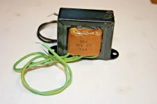
One secondary winding powers the ASC-1 circuitry and the other is for the motor power circuit.

As EB suggests in #39. I would simply unbolt the motor after moving the dish to the reference position. So you can set it all back up with limit switches aligned for it.
Put the ASC-1 on a table and wire the motor up directly close to it.
Hook up the bulbs to the motor terminals and run it. Give it a good voltage check. Stick a big honkin' screwdriver or a tool in the coupler and drag it down while its running.
Tap the limit switches firmly and wiggle the plungers. Give the motor housing a few raps. Or better yet just pop it open and check the brushes, springs, commutator. Loose magnets.
Everything to troubleshoot up to the controller can be done w/o opening it up or randomly swapping relays.
 
Last edited:
Maybe my suggestion was not clear. All you want to do is see if the actuator counts pulses in both directions. Nothing more than that.

Simple steps:
(1) Disconnect the motor leads to the actuator from the back of the Asc1. Leave everything else connected. Verify the Asc1 ON.

(2) Briefly Connect the actuator motor power leads to a dc voltage source and watch the front of the ASC1. The positioner counts on the front of the Asc1 should change immediately when dc voltage is applied to the actuator motor.
(3) Reverse the actuator motor power leads and test again. The positioner counts on the front of the Asc1 should change immediately when dc voltage is applied to the actuator motor.
<End of Test>

In a properly working system, actuator pulse counts go up or down, depending on the direction of dish travel. This test will cause the pulse counts to be added to one direction. The positioner pulse counts do not know polarity of the actuator motor, so they will be counted in one direction only which means the dish tracking will be off. Disconnecting the motor or doing anything else will not change this.


If you were real careful and did several additional steps, you might not upset the dish tracking pulse counts. Most likely though, the dish is already out of sync with the pulse counts as usually that is the case when there is a positioner problem.
 
EB. Unless you have special firmware. The counter will not increment unless the H bridge is active.
In no instance have I even been able to increment the counter with just the encoder and motor not energized.. If so, I would have been a happy camper.
Voltage will be present at the sensor terminals. But operating the encoder alone will not change the counter.

I had discussed this with you in the past pertaining to motor coast after the controller de energized it. Those little added gear train movements after the counter is stopped (but armature slows to a stop) add up and create count errors.
Bottom line. Motor is turned off by the ASC-1, the counter is immediately stopped. No matter if you move the encoder manually or power the motor externally.
As an addition. When searching for and peaking satellite positions before storing them. Positional errors for all other satellites that needed global tweaking before adding the brake reduced by a great amount.
This would occur every time the dish was 'bumped' a few counts at a time. Example. Not being able to lock a signal, but you know the satellite must be there from interpolation.
So you move it a little and perform a blindscan to see is a transponder was snagged. No? Move it a bit more and do it again. Until you finally do hook that fish. Then tweak it in.
Wondering if a V box does it differently.

FYI. When I added a dynamic brake inside of the motor housing in the form of a DPDT relay with the NC contacts connected in series with a .22 ohm braking resistor to the brush wires.
Errors from coast immediately decreased by a great amount.
This was to be a provision in the prototype ASC-1 as was the aforementioned (Brian) PWM mosfet in the motor circuit to coast up/down the motor. Which would have been damned nice to keep.
 
Last edited:
My apologies if my information is not correct!
I should withdraw from the conversation of fixing the Asc1 as it is not something I normally use. I am certain lme will find a solution!
 
And my apologies too. Good intentions, I know. Hope you accept the same.
I'm just a bit peed that the tech. on these is 'eyes only' still even after they were discontinued. Glad Brian is still supporting keeping them working.
They do have similarities with the V box movers. And is why it would be interesting to know if the counter did actually keep active after the motor is shut down.
Kind of seems not though because the counter wouldn't know which way to go since the encoder is pulse/switch closure only. Not a quadrature encoder like your ham rig would have for he VFO.
But. Try to trust me a little. Because my nose has been in deep with the ASC-1 to R.E. it. As far as the circuit and perpheral components go.
A few I've seen here that I worked on have solder pads lifted just because they felt like it.
And there's a bit of dodgy solder work where the various after mfg. mods such as 22 kHz pass-thru and such was done.
Just that I wouldn't jump to swapping relays w/o proper soldering equipment and practices go. Some of the pc board traces aren't very rework friendly.

The motor could be spun all the live long day in one direction on it's own power and counter not change one bit.
Until the E-W or receiver commands it to actuate. When the direction button is released the counter simply stops and the relays open.
In the case of a go-to command from a receiver. The controller doesn't know which direction the motor is running. Just that the encoder is providing pulses.
Break the sensor connection or stop the magnet and an error will show.
I do believe that there is an over current detection circuit though. Because I've seen 'motor stall' here and there. Different from a limit switch notification / error.

Again. My apologies.
 
Going back to my post #35, what is the purpose of the single transformer, and where is to be installed if needed ?

1 amp, 110 to 24 vac transformer for ASC1.webp

Thx.
 
I may be wrong but perhaps to replace one of the dual secondary windings of the existing transformer. Wired into the board power connector for the motor only circuit.
The secondary windings are specd. at 22 & 24 VAC. One to power the electronics, one to run the motor.
Most actuator motors are rated at 36 VDC. After the rectifier circuit in the ASC-1 the voltage will be a bit above 24 VDC. But once it reaches the dish. Depending on the cable used and length.
Voltage drop could be considerate. As well as current drop. The motor might exhibit even lower voltage when it is running if measured across the screw terminals in the motor housing.

I personally like the idea of the switch mode supply for the motor circuit if only because they allow a small margin of voltage adjustment and regulate current very well. Something that a transformer can't do.
 
Last edited:
Sounds like the East relay is going bad.

Eliminate the relays and see if the actuator moves correctly.
To test, remove the two power leads for the actuator from the back of the Asc1. Find some type of small 12-36 volt DC power source, and connect the actuator leads to the power source while watching the front of the Asc1. The counts on the ASC1 should change when power is supplied to the actuator. Then reverse the the actuator power leads, and test the opposite direction. Again the counts for the actuator should move on the front of the ASC1 is supplied.

Portable drill batteries and even a wallwart type dc supply can be used for this test. Move the dish close to the center of the satellite arc if possible for this test as that is the area that takes the least amount of energy to move.

I did the test today, and the counts on the display didn't change.
 
Unless the ASC-1 is commanded to move the dish. Aka: apply relay coil voltage on the h-bridge.
You can put your own power on the motor and the counter won't increment/decrement at all.
And. Again. You can spin the encoder magnet by hand all-the-live-longed-day if the unit is not commanded to actuate the relays.The counter will not move a single digit.
Motor/relays off. Counter deactivated. It's in the firmware.
Maybe a vbox works differently. But not this critter.
 
Think about it. The ASC-1 doesn't know if the motor is turning cw or ccw. Becuase the encoder is a simple switch closure. Not a quadrature encoder with leading/trailing pulse pairs.
Therefore. If it were true that you were able to simply put your Harley battery out at the motor. Unhook the to-the-house motor power wires. And give the motor juice. How could the counter know which way to move?
In the ASC-1 MCU. When it commands the relay pair to energize the coils and switch motor polarity and apply power out to the motor.
If it assumes that the actuator is going to move in X direction. The MCU flips into a counts up mode.
When the relay coils are activated to reverse and apply power to the motor. The MCU inverts counting. And down she goes!
You could choose to extend the actuator and have it count up. My choice. Or have it count down when extended just by swapping the motor polarity. The reed switch don't care.

Agreed, but just wanted to test EB's suggestion. I'm sure that the hole functionality of ASC is governed by the main chip response to the commands given to the unit itself. As long as an external source is operating the motor, it will not take any action such as to display a count or anything else.
 
I guess depending on how your motor is put together you could park your dish at its mechanical/electrical limit.
Then if you so desire mark exactly where the limit cams line up. Remove the microswitch screws and let the switches hang. Unbolt the motor from the tube.
And then power the motor up with your DC power source. And let it spin until the cows come home.
After that press the E-W buttons on the ASC-1 and it will count up or down w/o errors.

I'm wondering. Perhaps will read back for a refresher. Why would you think you need a separate transformer?
The motor drive side of the ASC-1 has its own bridge rectifier and smoothing capacitor. Using the 24 VAC xformer winding. The electronics side has a bridge of 4 separate diodes. That runs from the 22 VAC xformer winding.

If more motor speed were needed my choice would be to build an external H Bridge with cube socket relays or SSR's and a Meanwell 36 VDC switcher.
And keep the guts of the dish mover intact. But. That's me. Probably could kicad up a diagram in a few minutes.
 
Think about it. The ASC-1 doesn't know if the motor is turning cw or ccw. Becuase the encoder is a simple switch closure. Not a quadrature encoder with leading/trailing pulse pairs.
Therefore. If it were true that you were able to simply put your Harley battery out at the motor. Unhook the to-the-house motor power wires. And give the motor juice. How could the counter know which way to move?
In the ASC-1 MCU. When it commands the relay pair to energize the coils and switch motor polarity and apply power out to the motor.
If it assumes that the actuator is going to move in X direction. The MCU flips into a counts up mode.
When the relay coils are activated to reverse and apply power to the motor. The MCU inverts counting. And down she goes!
You could choose to extend the actuator and have it count up. My choice. Or have it count down when extended just by swapping the motor polarity. The reed switch don't care.

The test I described is valid for most G box and V box type positioners. The G box and V box type positioners were 40-50 dollars a few years ago, but are a bit pricey today. The pulses or counts go up on these type of positioners anytime the actuator is moved or something else is done to trigger a pulse. The pulses are recorded as counts on the front of the poaitioner when it is powered ON. The counts will be added all in one direction regardless of how the actuator is polarized. The pulse counts may be changed to add or subtract by pressing the east - west buttons on the front of the receiver or by using the positioner remote.

I remember my ASC1 performing the same way where the counts would be added or subtracted anytime the unit was powered on, but apparently my memory is flawed or I had an unusual software installed in it. Pulse counts need to be recorded at all times so any errors in the dish moving may be seen. Cutting the pulse counts off once the positioner has supposedly stopped is a dis-service to the user as any extra pulse count errors will be "unseen" and the operator will be left wondering what the hell is going on.

A stock ASC1 will produce about 100 watts if it is pushed hard enough. You will see this wattage at about 5 amps of draw and 18-20 volts dc output going to the actuator. This amount of power is a bit more than the V box or G box which can produce around 60-80 watts of motor moving power.

I have a Prodelin commercial with a dish weight of about 320 pounds. The dish is in 8 sections, and each section weighs a bit over 40 pounds when put on a calibrated refrigerant scale. The feed and other items puts the weight up to about 350 pounds without the mounting skeleton or polar mount included.

It takes more energy to move my type of dish as compared to most anything else a person will find in a backyard. A 10 foot mesh dish has a dish weight of 60-80 pounds, and some of the homeowner fiberglass will double that mesh dish weight or maybe a bit more. 12 foot home owner dishes will have a bit more weight than the ten footers, but hardly any of them will come close to the weight of a commercial Prodelin. In other words, you can make power modifications to any of the positioners mentioned in this thread, but in most cases, they are not really needed.

The parts shown in post 4 of this thread were installed in my ASC1. These two parts provide 180 watts continuous, with the transformer only being used to supply the low dc voltage needed power the ASC1 The small power supply provides a rated 180 watts continuous power, and provides a steady 35 volts dc while doing so. Peak power is 240 watts, which I have seen a time or two.

In normal operation, it takes a brief surge of about 180 watts to get the dish moving if it is 40 degrees or further from center. But this 180 watts immediately settles down to 100 watts or less. When the motor is moving across the center of the arc, around 40 watts of power is all that is needed. The dish moving is done with a 36 inch ball screw actuator by Venture.

I don't really suggest installing the parts shown in post 4 because they are not needed in the ASC1 unless you want to try to improve the dish moving speed. The ASC1 cannot hold its advertised 36 volts dc when powering the actuator with a ten foot dish attached. It can move the ten footer with east though, but a bit slower than a postioner that runs 35-36 volts dc all the time.

So my opinion here is LME should either fix the ASC1 or simply replace it with a V box. The ASC1 has great advantages when used with a corotor, but for just day to day dish moving, a V box will do that task with ease on most homeowner type dish systems. IMO, the V box type postioners have better software than the ASC1, but they also have less features. I don't recommend modding the ASC1 as shown in post 4 unless there is a reason for it. The only thing most people will see with these mods is an increase in dish moving speed.
 
Sorry man. Didn't mean to get all riled up. I've got those 3 defective ASC-1's here 'in the queue' to get running.
The first thing of thought when a simple slap-a-bigger-transformer-in-it was brought up is how small and fragile the pc board traces are.
There is over current protection built into the circuitry that provides feedback to the MCU.
Different from 'motor stall or sensor failure when the actuator slows or the encoder (reed switch) becomes flaky. Motor is Shorted. And LNB is shorted.
Something y'all Atlanter folksies never experience is when it gets below zero and the grease in the actuators becomes candle wax.
So. In my case. At first wrapping a heat tape around the tube and motor. Later just driling a hole for a zerk and pumping in super low temp. grease and flushing out the OEM stuff.
And just in case. Instead of the pulse sensor lag and returning an error. Because 1/6 revolution of the main drive coupling gear waiting for gooey, frozen, roofing tar grease to start flowing.
An encoder wheel with quite a few more ppr fixes that.
Although people up here do comment on how I lived in Florida all of those years. And how hot it is.
I just smirk and mutter. The hotter it gets, the less they wear. Wanna' buy a farm? I gots deers and turkeys and can fish out my back door and there are stars forever. And no friggin' rap 'music' and tomato can mufflers cruising by at all hours. A chopper spotlighted me in Orlando one night headed out to flop my butt on the Harley. I just waived. Warthogs were doing exercises over my fields, treetop level here. I traipsed up and gave 'em a salute. They gave me wing wags and hard breaks backs. Cool, huh!

Nevertheless. There must be a reason that even though most actuators are rated at 36 VDC. These gizomos, the Titiainum and vboxes, send out 24 volts transformer power.
On a side note. I laugh at the audio guys who spend $1500 and up for exotic speaker cable.
And never realize that the audio amps in their stereo have pc board traces that are a few millimeters wide. Maybe like 5. And a few thousands of an inch thick. Mixing imperial and metric is fun.
And once inside of the speaker cabinet. The wiring is 16 gauge.
Kinda' like hooking up a fire hose to the hose spigot on the side of your house. Running it out to the garden And hooking up a 5/8" watering hose to soak the termaters.

Anyway. Relays going bad and digging inside and cooking pc board traces by those less experienced. Splicing in a super inefficient and higher voltage transformer to add load to already weak (but adequate within its design) pc board. Could be eliminated by an easy couple of evening or weekend project.
Duplicate the internal relay circuit with solid state relays, perhaps a hard contact relay for motor reversal and socket. A robust switch mode power supply that provides voltage and current regulation and compensation. All in a compact outboard assembly. I get riled once in awhile. It's all good though. There is that KMA option below which I really like!
 
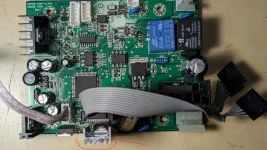
After my problem with "...reach the limit.." error message, another problem: when the dish was traveling for more then ~30° from one position to another, the display was blinking, went dark, but after the dish reach the destination, display was lit. No signal at the destination point and trying to fine tune the dish, realized that asc lost the counts for the position.
Looked inside asc, and found that one component was kind of lose on the circuit board (see arrow):

1.webp
Noticed that this component is very close to the main transformer; maybe to much heat from transformer ?
I soldered back the 3 legs of the component and for the last 2 days, no more errors or display problems.
What do you guys think ?
 
Last edited:
After my problem with "...reach the limit.." error message, another problem: when the dish was traveling for more then ~30° from one position to another, the display was blinking, went dark, but after the dish reach the destination, display was lit. No signal at the destination point and trying to fine tune the dish, realized that asc lost the counts for the position.
Looked inside asc, and found that one component was kind of lose on the circuit board (see arrow):

View attachment 18133
Noticed that this component is very close to the main transformer; maybe to much heat from transformer ?
I soldered back the 3 legs of the component and for the last 2 days, no more errors or display problems.
What do you guys think ?

I found that variable voltage regulator to be misaligned in several PCBs. Soldered to the board next to the thru holes they should be mounted in. I had one break during use. That brought my attention to it and I found others with a similar problem.
 
There is a fix to improve the LCD display contrast. Thought I would write this down before I forget it. On the LCD pcb remove R3 (222) and replace with (472).
 
.
Something y'all Atlanter folksies never experience is when it gets below zero and the grease in the actuators becomes candle wax.
So. In my case. At first wrapping a heat tape around the tube and motor. Later just driling a hole for a zerk and pumping in super low temp. grease and flushing out the OEM stuff.
And just in case. Instead of the pulse sensor lag and returning an error. Because 1/6 revolution of the main drive coupling gear waiting for gooey, frozen, roofing tar grease to start flowing.
An encoder wheel with quite a few more ppr fixes that.
You are probably running an actuator that is operating beyond its lifespan. That is why you had to pump it full of grease. I doubt you find find a grease fitting on a new heavy duty actuator. They are sealed units and what they have in them is supposed to last the lifetime of the unit. You are living the example of why they don't have grease fittings anymore: Cold weather.


Nevertheless. There must be a reason that even though most actuators are rated at 36 VDC. These gizomos, the Titiainum and vboxes, send out 24 volts transformer power.pc board.
The reason is cheap. Vbox type Positioners are made from the cheapest materials known to man. Disassemble one sometime and you will see...

I never fully understood the ASC1 either. The stock transformer weighs something like 6-8 pounds. WHY? I have been running the small power supply's shown in post 4 of this thread for years without a failure The cost of one of those supplies was about 20 bucks or less when I bought them. They do a fantastic job of providing the needed DC voltage and watts to power satellite actuators. A satellite dish positioner is all about start-up. It only has milliseconds to move or you get a failure. Twenty something volts and an amp or two for current in cold weather probably doesn't cut it for some folks --even when using a mesh dish that is not very heavy.
 
You are probably running an actuator that is operating beyond its lifespan. That is why you had to pump it full of grease. I doubt you find find a grease fitting on a new heavy duty actuator. They are sealed units and what they have in them is supposed to last the lifetime of the unit. You are living the example of why they don't have grease fittings anymore: Cold weather.

Well. To counter that. Actually. One train of thought would be yeah. 5 years, swap it out. Except for the same dish my mom and dad had installed back in the 80's is still standing. And I use it today after some mild refurbishing. There is literally a box of actuators from Venture, Von Weise, Saginaw Gear, "Houston Tracker". Dad just wrapped a heat tape and sliped pipe insulation over it and ran an extension cord to keep it warm in the winter.
Funny. "End of life". No maintenance. Run 'er 'till she pukes. Installers back in the day loved it. It gives you crap. Call him. He shows and swaps the unit out. Resets your positions. And bills you.
If you didn't move that dish in the cold cold winter. No problems. Wait 'till spring. Or. Slap on a heat tape (even on a brand new replacement) and punch Satcom 4. Ba-da-bing!

Go ahead. I dare you. I challenge you. Take an aged but working fine actuator-du-jour. Throw it in the deep freezer and get it down to -10f. Give it some pixies.
You've probably never (or remember) trying to start a car in subzero temperatures. "ER-RRRR-RRR-RR-R....*Start*. IFyou're lucky. Not so lucky? After a few cranks...*click click click*
Charger time. And starting ether. Jesus! Automatic tranny's don't even have dipsticks anymore. And factory recommendations to never change the sauce in them. She pukes, swap 'er out.
Goodfellas...."eff you, pay me". Fred at your local independent service facility with beer in the fridge who happens to know and love your type of vehicle knows better.
Pull the pan. Dump "at least" some of the juice. And refill it. And 4 grand pending turns into a hundred-fifty bucks and 200k miles before trading in.

So. A drill. A zerk. A grease gun loaded with Lucas super low temp grease that looks like a nasty sinus infection discharge. Not exactly a bad thing. And it works. Tear down the motor. Clean and grease it. A pair of brushes from the auto parts or hardware store assortment. I rest my case.
Is a polar mount worn out when the pivots are sloppy and the bronze bushings are all hob-wobbly? Thirty bucks for pillow blocks. A few bucks for hardware. Center punch a few dimples. Drill a few holes. ratchet strap and c-clamp a few things in place. Mr. DeWalt and some sharp drills.
What would you think if I were to come out and condemn your Prodelin because the pivots were toast? Look at my quote for a new General Dynamics 12 footer. Nah. I don't think so.
Oh yeah. This is all grain of salt and backbone. Please don't turn into a shrinking violet.
I'm a living example of my economy is not disposable. American Ingenuity. Dislike for planned obsolescence. Drinking a cold beer under a shade tree from a recycled Hyundai and Kia.
One stinkin' hole. A grease fitting. Some pumps of goo. And Venture waits another day.


The reason is cheap. Vbox type Positioners are made from the cheapest materials known to man. Disassemble one sometime and you will see...

I never fully understood the ASC1 either. The stock transformer weighs something like 6-8 pounds. WHY? I have been running the small power supply's shown in post 4 of this thread for years without a failure The cost of one of those supplies was about 20 bucks or less when I bought them. They do a fantastic job of providing the needed DC voltage and watts to power satellite actuators. A satellite dish positioner is all about start-up. It only has milliseconds to move or you get a failure. Twenty something volts and an amp or two for current in cold weather probably doesn't cut it for some folks --even when using a mesh dish that is not very heavy.

The Vbox I can 100% agree on. It's open source and readily available for cheap to nothing to design and program. They work. The code is locked in the MCU by whomever decides to clone them.
Could they be made better? Certainly. Could they have a nice display like the ASC-1? Probably.

The ASC-1? It's a love/hate for me. All I want to do is repair a few. Reverse engineering the circuitry took a bit for the sections that show faults. And the whole design is "eyes only". I will need Brian's assistance after getting the circuitry aced. One, maybe two need microcontrollers. Not so hard to do with the right equipment and skill.
It's a Vbox in essense. With some really cool bells and whistles.
The motor power side is rectified xformer voltage. No regulation to speak of and prone to voltage/current sag. Something that a SMPS would handle most awesome. Plus just sitting in the case it sucks juice and makes heat. Again. something that SMPS supplies do very well in management of idle current.
And in agreement of the millisecond lag dish movement error generation. Try it when your motor grunts trying to get that negative-twenty molasses squishing.
Instead of drooping voltage and current running through X feet of cable. An smps senses it and compensates. Everyone needs a little boost once in awhile.

Vbox. Cheap. They work. No big sting if one takes a crap.
Make your own from a PIC mcu. Bare PC boards are out there.
Adruino. Now. That catches my interest. The diseqc library is freely available. Projects abound. Some are pretty cool.
The Research Concepts commercial dish movers. 1 axis, 2 axis. Ebay has quite a few nice ones for not too bad of a price.
It was mentioned. Reading from the FTA guys who use them. Pretty robust. Although you have to manually punch up a memory store to move your dish.
But they do have pc software and a RS422 interface. Bing!
Once i get the interest of the right Arduino guy I'll get very involved. Diseqc works on a data string. ASC-1, Vbox "listens" for the command to move to a memory location.
The Arduino motor control projects do the same thing.
It's all there for the Arduino. Instead of waiting for a go-to command and actuating relays and counting encoder pulses.
Let the Arduino receive the command. And relay it transcoded to a RS422 string that a RC mover understands. The data packets of diseqc are very similar to RC controller protocols. But different.
A display on the Arduino showing a command was sent from the receiver to move to SES-1, etc. And the RC mover doing it. No more dead Vbox. No more hoping that your ASC-1 wont die of sudden death.
Arduino guys please speak up!
 
Back
Top