el bandido
TNAP-Images
I have a pair of Norsat 8000RI lnbs attached to Eagle stage 2 5G bandpass filters. These lnbs are attached to an old Radio Shack multiswitch to feed the fta receivers. Recently I lost about 3-4 db(snr) on the horizontal side for no apparent reason. Finding the cause of the signal loss is pretty straightforward, but is complicated a bit with the 5G filters installed in the system.
Adding the 5G filters creates a loss that cannot be recovered in the range of 1-1.5 db(snr). The 5G filter loss is hust something that you have to live with. A 5G bandpass filter is basically a piece of metal that allows certain signals to pass while rejecting other signals, hence the name bandpass. To go further, a bandpass filter could be considered to be a tuned piece of metal, so it also has to be checked anytime there is an unexplained loss of signal in the antenna system.
For signal loss, start with the basics of the coax feed. We can almost immediately rule out the main run of coax because the vertical side of the antenna system seems to be working correctly. Installing a barrel connector to eliminate the Radio Shack multiswitch shows individual testing of both horizontal and vertical polarities to be about the same with the multiswitch installed. This test sort of eliminates the main run of coax and the multiswitch.
There are two short runs of coax between the lnbs and the multiswitch. These two runs were swapped on the lnbs and the two polarities rested individually again with no apparent changes and with the horizontal loss still present. At this point, we can almost 100 percent rule out a coax or connector problem.
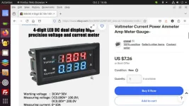
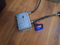
Current draw will usually fall or become noticeably higher when a lnb is sick or failing. A voltage/milliamp meter was installed to test voltages from the receiver and current draw of the lnbs. The vertical and horizontal voltages are correct, with a little over 18 volts for horizontal and a little over 13 volts for vertical.
The vertical lnb showed 111 milliamps of current draw and the horizontal lnb showed 110 milliamps. The receiver was rebooted in both milliamp tests, with the vertical lnb holding at 111 milliamps and the horizontal lnb dropping to 85.3 milliamps. Both lnbs were tested on the same 18 volt side, which is horizontal in the receiver. At this point, it seems the horizontal lnb is sick, but you have 5G filters installed which means more work is needed.
Testing at this point would be complete and we could say with a certainty the horizontal lnb needs to be replaced. But what if the lnb isn't bad and the problem is really the filter? What will need to happen next is the lnbs will need to be removed from the dish and swapped. Move the horizontal lnb to the vertical lnb location and move the vertical lnb to the horizontal lnb location. The 5G filters should remain "as is" and not be moved. Then the lnb assembly needs to be installed back in its original position and retested.
Once the lnbs are swapped, the signal loss should follow the lnb (if it is bad) with the vertical side of the antenna system now having the signal loss and the horizontal side of the antenna system operating normally. If nothing changes after swapping the lnbs, and the horizontal side still has signal loss, then the 5G filter on the horizontal side most likely has a problem. Then and only then should the 5G filters be swapped and testing should show the signal loss following the location of the sick 5G filter which is now on the vertical side of the antenna system.
So at this point I am down to swapping the lnbs, which means removing the feed from the dish, unbolting and swapping the lnbs then reinstalling everything as it was. It is very important to mark things before disassembly or removal lest you get confused about the original location of the parts Finding the source of the signal loss becomes more complicated with the 5G bandpass filters installed, but it is doable by the process of elimination.
This is a busy time of year for me, but hopefully I can get the lnbs swapped and tested in the next day or two. Extended band lnbs are useless with 5G filters installed because only 200 MHz of band is usable. These lnbs have a l.o. of 5750 which means I will need to buy 2 lnbs if one is bad, or buy another basically useless 8000RI.

